Ceiling Fan Wiring Diagram With Capacitor
Ceiling fan wiring diagram with capacitor
In the post, you will learn about the complete wiring of a capacitor with a ceiling fan. This post contains a simple ceiling fan wiring diagram with a capacitor. As you know there are two types of winding in the ceiling fan “main winding” and “auxiliary winding”.
The connection between two windings is called the “common” point and the other ends of “main winding” are called “Run” and the “auxiliary” winding end is called “start”. The supply goes is connected to the “common” and “run” points. And the capacitor is connected between the “run” and “start”.
How to connect a capacitor to a ceiling fan diagram
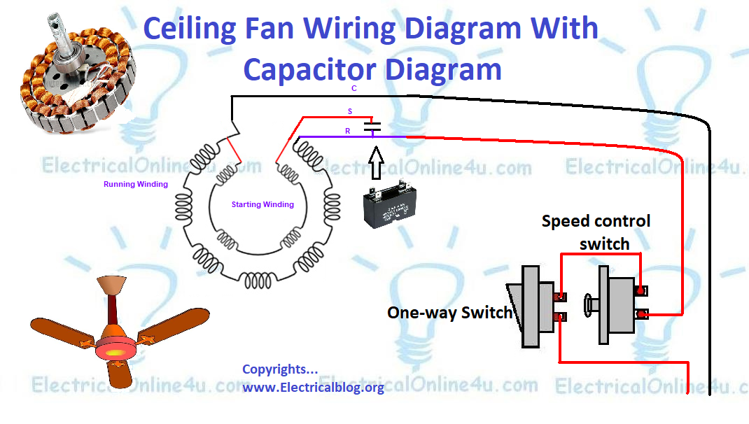
In the above ceiling fan capacitor wiring diagram, I have shown how to connect the capacitor to the ceiling fan, and how to wire a ceiling fan with a one-way switch and speed controller (dimmer switch). In the above diagram, I showed the running and auxiliary windings.
If you want to find out the Start, Run and common connection in a fan using a multimeter then also read the below article.
Also read:
Single Phase Motor Winding Diagram | Main/Auxiliary Winding Connection
How To Identify Start, Run and Common
How to wire a ceiling fan video tutorial
Here is a video tutorial in the English language, which help you more to understand the complete wiring diagram, So for better understanding kindly watch the below video tutorial.
I hope after watching the video tutorial, now you will be understood, however, If you have any questions according to this post, you can ask your questions in the below commenting system.